Rotshaft Learn & FAQ
Rota-Shaft clamps are engineered to provide a controlled combination of rotary/linear motion in machine tool clamping and fixturing. In applications requiring this compound motion, The Rotashaft gives you the flexibility of a variety of motions with one clamp – which means one specifically-designed clamp can be used in many different applications with the proven engineering, price, and off-the-shelf availability of a standard component.
Rota-Shaft consists essentially of four parts: a rod, a housing with cam track, a hardened pin and bushing, and in powered models, a mounting adaptor plate. The parts can be assembled in a variety of ways to provide specific combinations of linear and rotary motion. Changing straight travel distance or amount of rotation requires altering the stroke of the cylinder. This can be achieved by placing a spacer between the cylinder head block and the Rota-Shaft mounting plate. Rota-Shaft motion is controlled by the pin and bushing moving through a harmonically-machined cam track in the bushing. By changing the relative position of the pin and bushing at the beginning and end of the stroke, you change both the straight travel distance and amount of rotation.
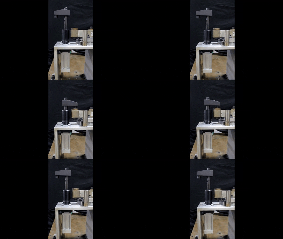 | 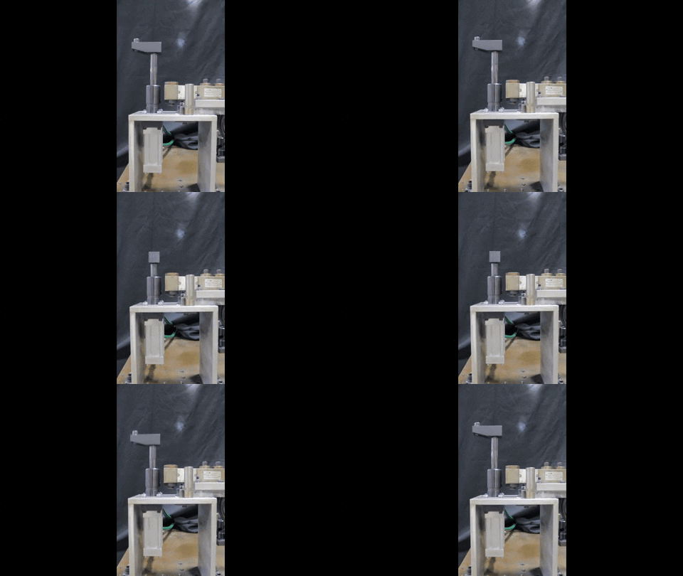 |
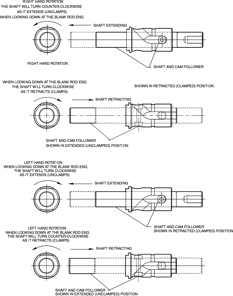
Rotation is the direction in which the clamping details rotate when traveling through the rotational portion of the cam track into the straight travel, clamping section. The example below shows right hand rotation.
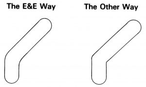
The cam tracks machined into all Rota-Shafts are controlled by a precision, 4-axis, CNC-generated helix. This minimizes clearances between the hardened steel bushing and the cam track and eliminates the chance of an imperfect fit. It also ensures a smooth, impact-free transition from linear to rotary motion. The geometrics involved in generating a perfect harmonic path require the calculation and plotting of the radial transition of each bushing to prevent flat spots on cam surfaces. To determine specific degrees of shaft rotation, this factor must be included. E&E engineers will gladly assist you with this calculation.
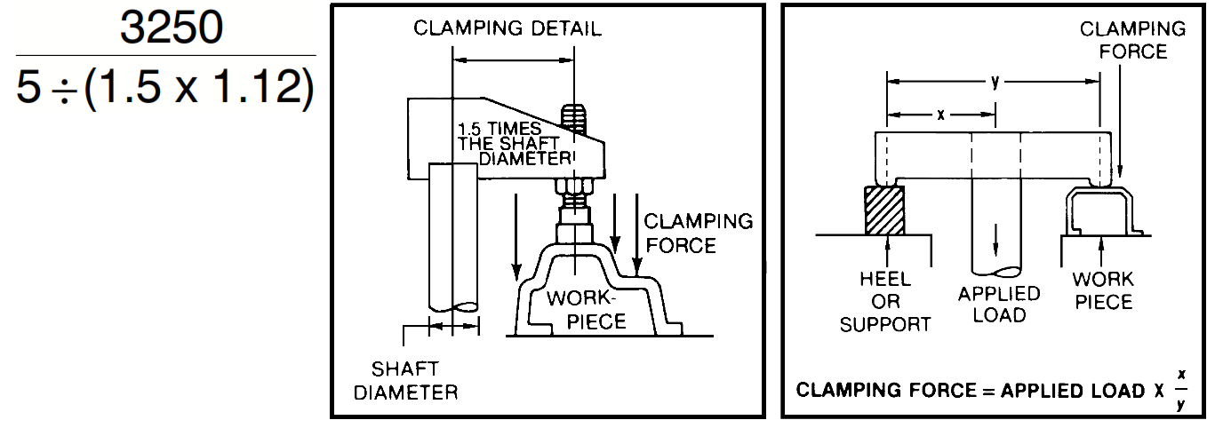
In heeled clamping applications, the applied load is limited only by mechanical connections and the driven member. To assist in the sizing and selection of Rota-Shafts the following maximum Clamping Forces have been calculated.These values are based on a clamping detail offset 1.5 times the shaft diameter.
To calculate maximum recommended loads for applications requiring longer clamping details, divide the appropriate maximum load value shown below by the length of the clamping detail, e.g., a 5” long clamping detail used with a 1-1/8” diameter shaft would have a maximum recommended load of 1092 lbs.
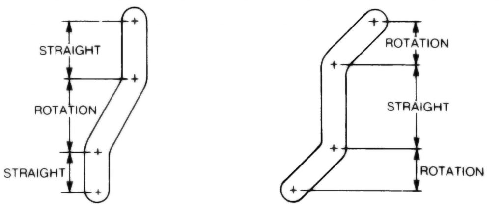
Choose any of our clamp configurations and lay in your own requirements for travel and rotation. Our Engineering and Technical Service Department will be glad to assist in designing the best clamp for your application, and should be consulted to insure your requirements are attainable.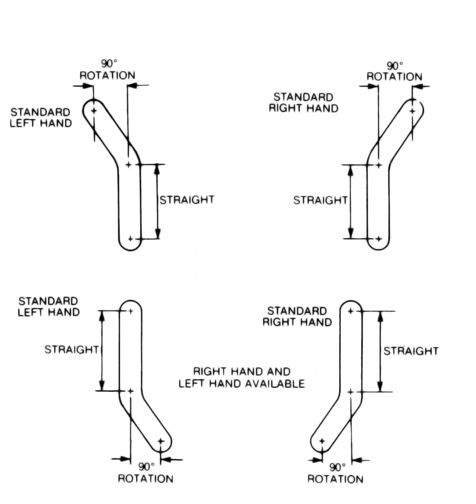
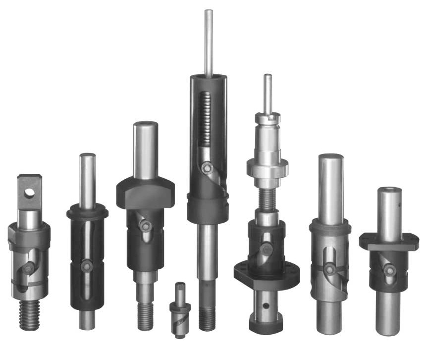
These are just a few of the thousands of custom designed Rota-Shafts we’ve made for others in both powered and non-powered models.
Accordion Content
Accordion Content

